Junior
  
Currently Offline
Posts: 117
A+'s: 1
Joined: Jan 9, 2012 18:18:11 GMT -6
|
Post by dryshave on Mar 29, 2013 10:23:05 GMT -6
just having problem with spark right now - thought I had it yesterday, she coughed a couple times with "quickfire" and now no spark. Back to the manual
|
|
Junior
  
Currently Offline
Posts: 117
A+'s: 1
Joined: Jan 9, 2012 18:18:11 GMT -6
|
Post by dryshave on Mar 29, 2013 10:21:05 GMT -6
One minute I'm getting good spark and so I mounted the tank, got everything connected and fuel pump working.... coughed once with "quickfire" and then now just keeps rolling over.
I've tested the coil and am suspect of a wiring connection to the coil.
(already made sure kill switch was in proper position)
Wondering if I hooked up a test light to the power wires to coil if I would or should get a flashing test light when I cranked it over (testing power circuit to coil)?
It was nice to hear it sputter, but would have been nice to hear her roar to life.
I'll swap out the cdi unit and the rectifier. I've checked all the wiring and no obvious suspects.
Is there another way of testing the firing circuit to the coil, that I'm not finding in the manual
- BTW - I pulled the engine again, wasn't feeling as if the engine was rolling over right, re checked the timing and pretty sure I was one tooth behind the firing sequence. Sounds better when cranking too.
Trying to solve the electrical this weekend (no show on the brass pieces). Everything is in final position, wiring, fuel lines, cooling hoses etc.
|
|
Junior
  
Currently Offline
Posts: 117
A+'s: 1
Joined: Jan 9, 2012 18:18:11 GMT -6
|
Post by dryshave on Mar 26, 2013 18:26:40 GMT -6
WIRING HELL! I had to completely dismantle the harness in an effort to locate a problem getting power to the starter relay. Fixed that, then it was the start button, fixed that, then it was the headlight, fixed that, then it was no spark, fixed that, then it was the headlight again, fixed that ... and so it went for the past two weeks.... FINALLY! all the lights work correctly, I had to rewire the starter button, completely stripped and cleaned both handlebar switch assemblies, cleaned the harness connector, and tested all components for continuity and output. The only problem now has to do with timing (pretty sure I screwed up on the compression stroke - timing mark) think I set it on the exhaust) but at least I don't have to tear the harness apart to fix that. The parts are at the foundry, just waiting for a call, but pretty sure I should have them back by the weekend. Hoping to hear the scooter cough or sputter sometime over the weekend. Got the next 5 days off - so it's back to the bodywork. I'm hoping to have all the bodypanels finished for paint by the end of april or mid may (noW the brake lights not working AAAAAAARRRRRGH) 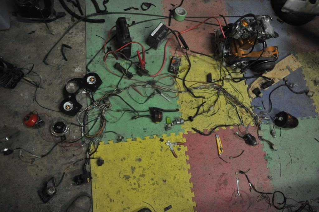 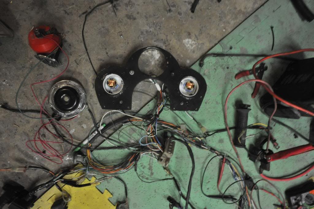 |
|
Junior
  
Currently Offline
Posts: 117
A+'s: 1
Joined: Jan 9, 2012 18:18:11 GMT -6
|
Post by dryshave on Mar 15, 2013 15:07:10 GMT -6
Once I figured out (duh!) that the Y/R was simply a power supply to the starter switch I was able to trace the path all the way to the switch itself. It appears to be a dud even after stripping it apart and cleaning all contact points. My solution - bypass the starter button on the handlebar for a push button on the dash wired to the Br/Bu wire which is hot. That way everything still works through the key switch. I'll try the other start switch first, before giving up. At least I know the wiring harness works didn't say it's correct, just that it works.
I will do the final clean up of the frame this weekend and final paint. Sunday I drop the pieces for the brass work and hope to have them back by next weekend.
|
|
Junior
  
Currently Offline
Posts: 117
A+'s: 1
Joined: Jan 9, 2012 18:18:11 GMT -6
|
Post by dryshave on Mar 14, 2013 23:41:56 GMT -6
have tested the switch and the switch is fine. I suspect the electrical circuit to the switch somehow.
Will know tomorrow when I install the elite parts and switch out the relay wiring....arrgh!
I have already converted the elite 250 wiring diagram to an illustrator file in colour, the type is clear and much easier to read. I am now doing the helix wiring diagram, though it is difficult to read the type on the original. I will offer both of them up for anyone who would like a copy as soon as they are completed and confirmed accurate.
|
|
Junior
  
Currently Offline
Posts: 117
A+'s: 1
Joined: Jan 9, 2012 18:18:11 GMT -6
|
Post by dryshave on Mar 14, 2013 19:02:33 GMT -6
 Well what can I say... it didn't start up as I wanted. The good news... all the keyed auxiliary power items work - lights, horn, turn signals, gauges, brake light switches, etc. That's the good news! The bad news... no start button power to the starter. The starter does work when jumping the starter switch posts (no long cranks as I am only testing continuity - so I don't know if there's spark etc). I've ripped the entire harness apart (SHITE!!) for the second time and checked all connections. I've since discovered through cmsnl.com that the bystarter / coil and stator are different between the helix and the elite 250. I know the stator is helix so I need to check the coil and bystarter to make sure I haven't swapped the parts. I am testing the wiring harness CONNECTED TO THE MOTOR - OFF OF THE FRAME spread out on the shop floor and grounded to the starter motor mount - is this the problem with connectivity or ground? I will check the pieces when I get home tonite and see if they're different. I will also have to swap the starter switch to the helix and adjust the wiring harness to compensate for the built in fuse connection on the helix. I used to love the challenge of wiring until I ran into this hornet's nest. I had read on another scooter site that the stator and auto bystarter were interchangeable, but the codes don't match. c'est la vie Will update my tech issues with the steampunk scooter here and leave the pic updates in the photogallery if that is OK with the admin.
|
|
Junior
  
Currently Offline
Posts: 117
A+'s: 1
Joined: Jan 9, 2012 18:18:11 GMT -6
|
Post by dryshave on Mar 8, 2013 15:46:49 GMT -6
had to bolt the rectifier to the back of the running board, it'll be covered by the rear panel, but still have plenty of airflow. Thinking of starting another thread as this ones getting a little long in the tooth. Steampunk 2013
|
|
Junior
  
Currently Offline
Posts: 117
A+'s: 1
Joined: Jan 9, 2012 18:18:11 GMT -6
|
Post by dryshave on Mar 8, 2013 15:44:53 GMT -6
justbuggin2..... luck and the patience of Job I'm thinking. At least I know the starter works, just need a pot of coffee, wiring diagram, voltage meter and start working from the starter out. Here's where I tucked the fuel pump and routing path for the wiring harness 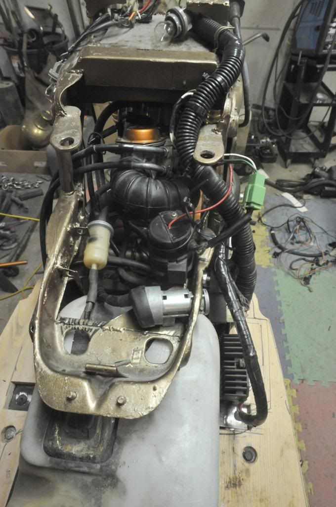 |
|
Junior
  
Currently Offline
Posts: 117
A+'s: 1
Joined: Jan 9, 2012 18:18:11 GMT -6
|
Post by dryshave on Mar 7, 2013 19:41:38 GMT -6
found where the red wire goes to, when I was dismantling the old helix wiring harness. It connected to the Br/Bu wire - according to the wiring diagram, it connects to the battery switch on the ignition... makes sense I guess.
Got all the wiring harness finished and everything tests for flow through. Fuel lines are complete as well as the cooling system. Will top up the oil / top up the rad and give everything a once "more" over, before trying an ignition test this weekend.. fingers crossed.
|
|
Junior
  
Currently Offline
Posts: 117
A+'s: 1
Joined: Jan 9, 2012 18:18:11 GMT -6
|
Post by dryshave on Mar 6, 2013 19:39:06 GMT -6
here's a couple quickie updates. Tightening up the wiring harness and have been confused by this wire for a while. The fuel pump is from a helix and the red wire coming out the top. It's not normally there, so I've photoshopped what I have. The wiring to the plug is all correct, but where the heck does the red wire go to? is it supplying power to something else? I wished that I had taken a picture of before removing it from the helix.... any ideas? 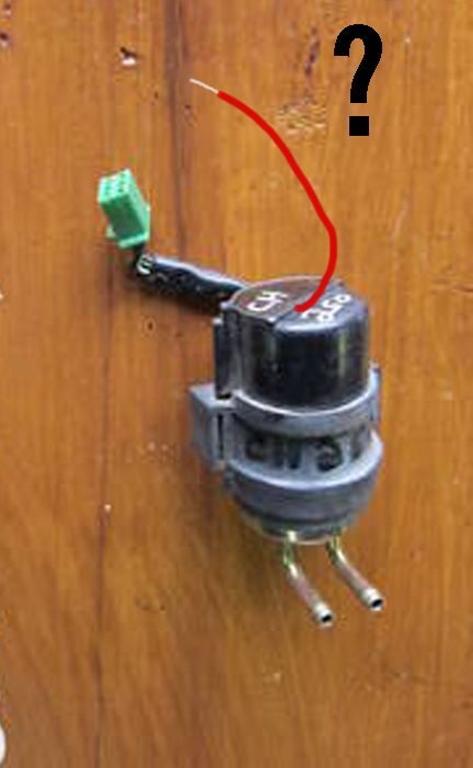 This is the design concept for the grill. I'm planning on having it cut by a water jet (same as one used on Senior vs Jr)... gonna have to save up for that one, probably get it done by the end of June - Mid July which is when I expect to have it on the road. 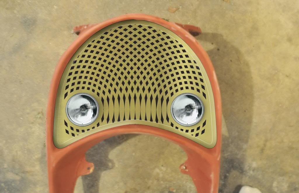 Of course the speedo says "warp speed and reality check", I will probably up the last indicated speed to 140 kph, but anything beyond that.... is a strong tail wind on a steep downhill run. Besides if I'm goin' that fast, how they gonna take my picture  |
|
Junior
  
Currently Offline
Posts: 117
A+'s: 1
Joined: Jan 9, 2012 18:18:11 GMT -6
|
Post by dryshave on Mar 5, 2013 18:39:22 GMT -6
Thanks for the compliment trailhead mike - more cool stuff to come! Was hoping for better photos of the gauges... but only managed to get one of the speedo - still a little out of focus - I'll take some better ones next week with a flash and proper setup. Have finished what I hope is the last piece to cast - the front fender. In the pics you can see the casting process - which after a year I am sure all of you are familiar with - I was able to pull the positive cast out of the mold over the weekend and unfortunately forgot the disk with the pictures on them. The good news is new keys cut and ready to get everything in place to do a run test this coming weekend.... fingers crossed. A couple of the new photos show the final mockups for the brass casting.... they go off to the forge on the 15th. Can't tell you how excited I am to seeing the finished pieces... I can get on to final sanding and assembly on the panels. Getting the seat out for upholstery next week as well and success!!!! I have come up with the front grill design, that pics on the other disk as well. Will upload the image later this week. I grabbed some foamcore and started cutting and drawing, took three templates until I hit the right one, I've got pictures of all three, so you'll see the development process. The plan is to have it waterjet cut - THAT's gonna cost me, but it's the only way to do it. Waiting to open the doors up and ready to start seriously sanding and ready for paint soon. 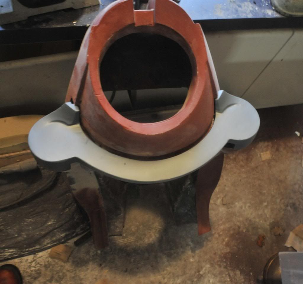 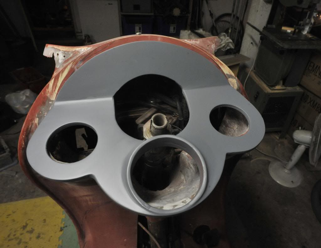 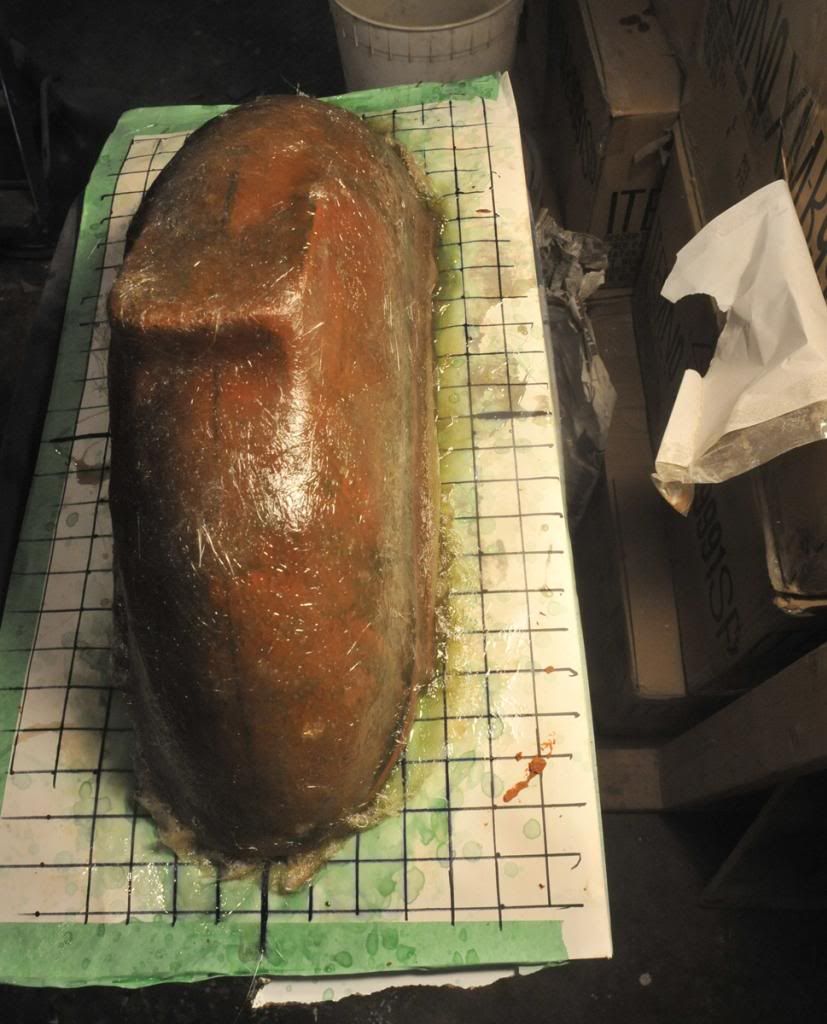 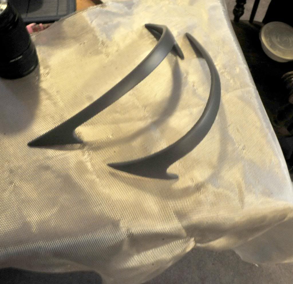 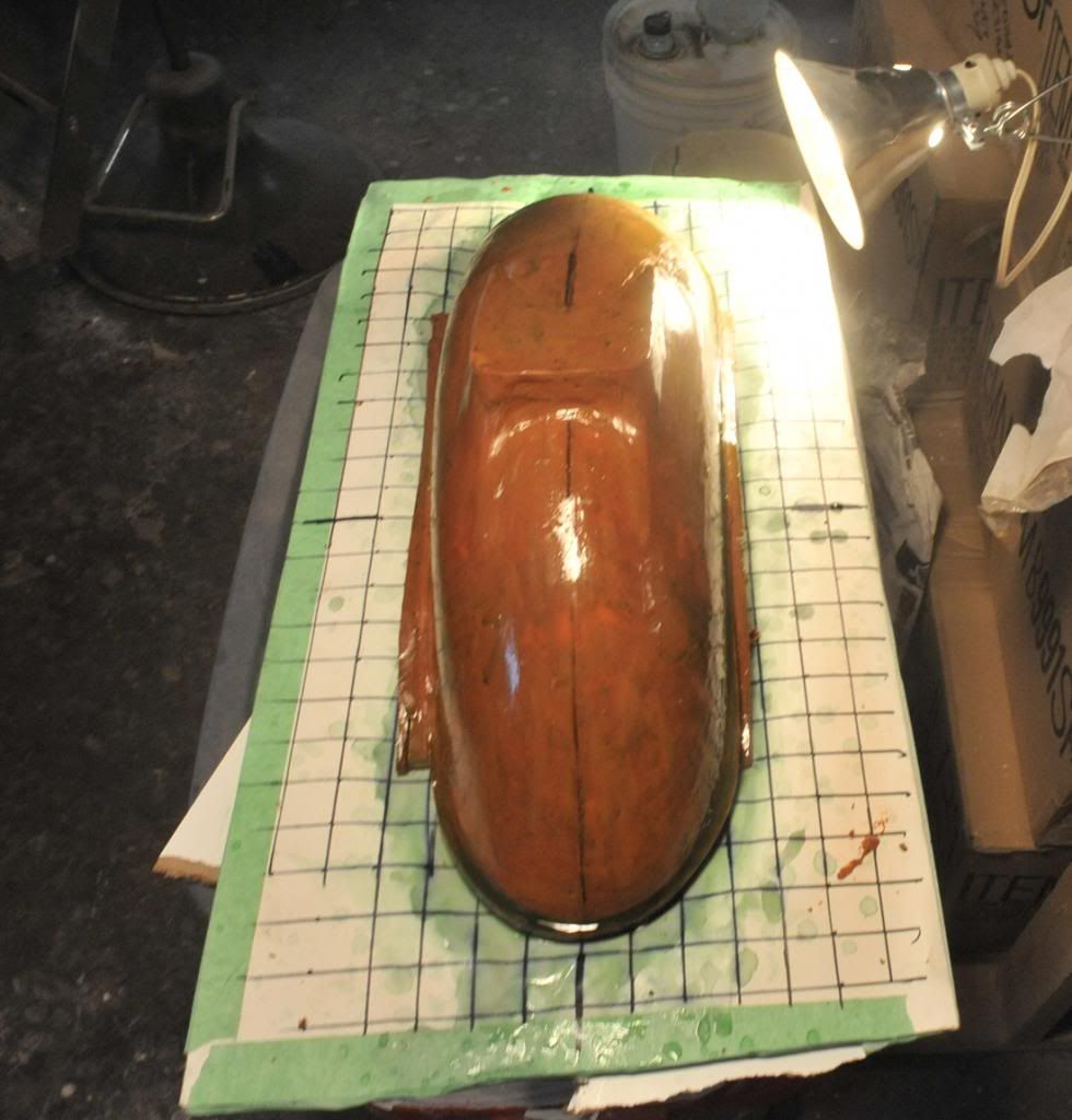 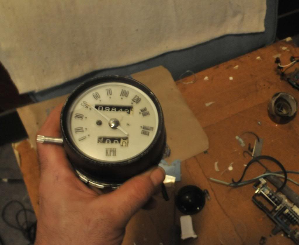 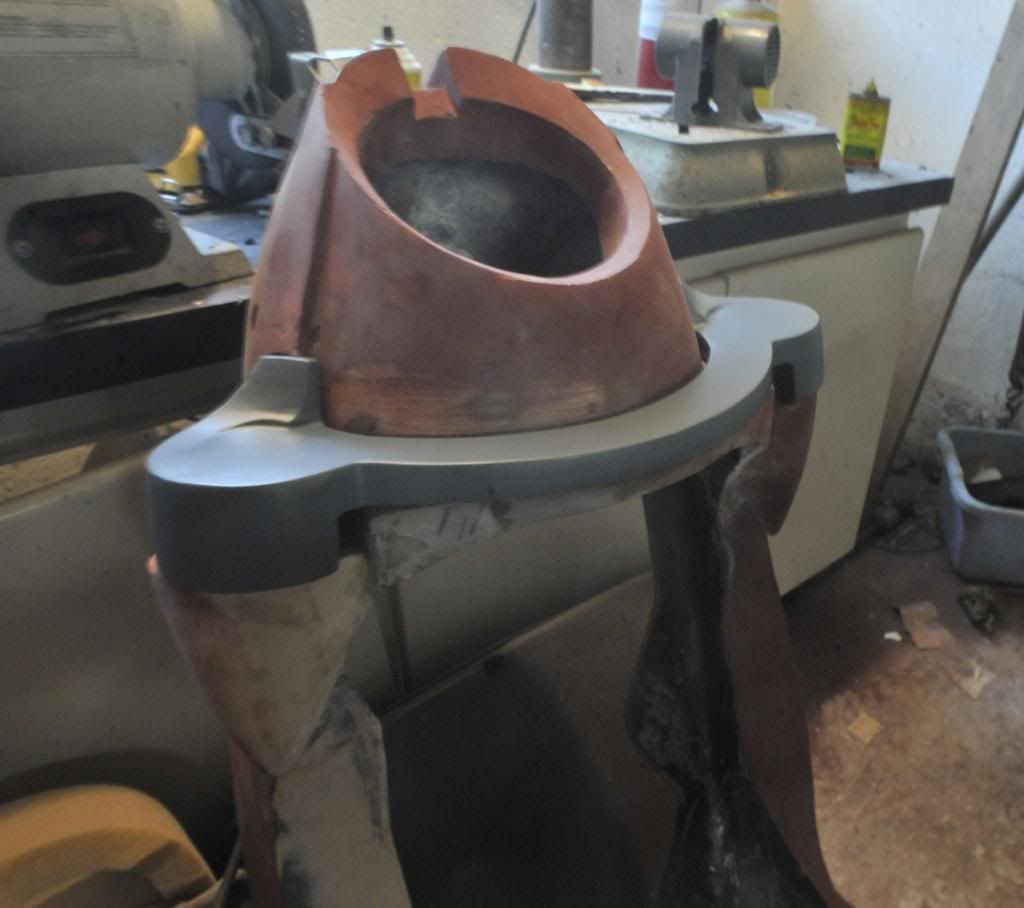 |
|
Junior
  
Currently Offline
Posts: 117
A+'s: 1
Joined: Jan 9, 2012 18:18:11 GMT -6
|
Post by dryshave on Feb 19, 2013 17:20:26 GMT -6
justbuggin2 - I couldn't agree more, I would like a pair there myself  I could see a tear drop shape speaker cone to match the headlight bucket I made (but have the teardrop shape facing the other way. madcollie - Thx man! It took me a long time to figure out the support configuration - I salvaged the metal curls from a coffee table I spotted on CL. It was the table legs that gave me the idea to incorporate the headlight and the windshield support into one. Not a lot of photos today, but promise to upload the rest of the batch this week... Finished off the gauge faceplates, they are ready to mount, but I won't seal them 100% until I have completed road tests and temp tests for gauge accuracy. Working on completing the positives for the 4 pieces to be cast in brass (scheduled for the end of february - getting excited to see them finished). The dash is 100% complete, the brows are finished and I am doing the last sanding on the tail section before priming. I decided to do a slip cast of plaster over all the pieces and then finish sand them with 320 and spray them with spot filler primer. It filled the scratches and smoothed out the finish nicely. The intent of the additional slip cast was to compensate for the shrinkage that will occur through the casting process. They look as good as I could have hoped. She'll be ready for paint as soon as the castings are back (first week in March) so it's time to nail down the grill and front fender ideas. Topping up the oil and ready to properly test the engine and wiring harness functions over the next couple of weeks, now that the dash is complete. Will post a video when she's ready for it. 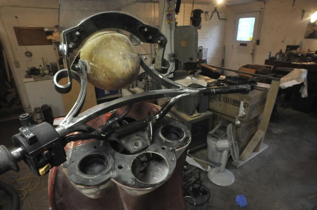 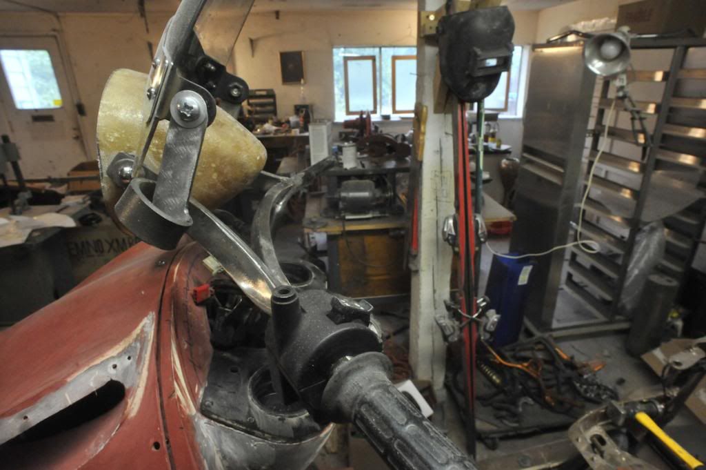 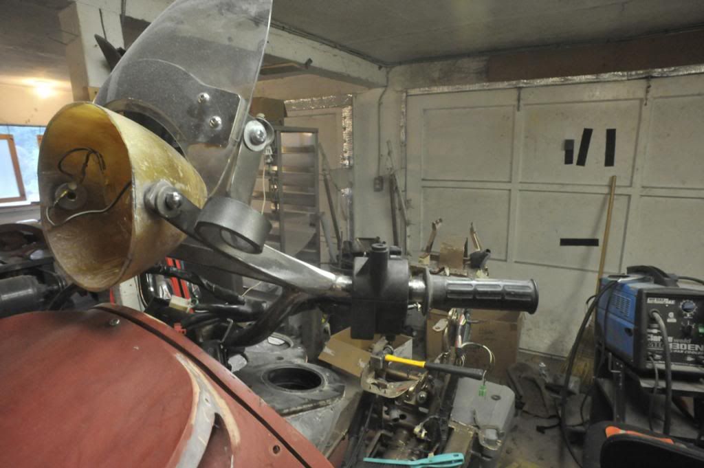 |
|
Junior
  
Currently Offline
Posts: 117
A+'s: 1
Joined: Jan 9, 2012 18:18:11 GMT -6
|
Post by dryshave on Feb 13, 2013 18:20:05 GMT -6
I built the new bullet shaped bucket right over the original chrome one (that plus plasticine). Should be able to pull the casting on friday.
|
|
Junior
  
Currently Offline
Posts: 117
A+'s: 1
Joined: Jan 9, 2012 18:18:11 GMT -6
|
Post by dryshave on Feb 13, 2013 18:18:48 GMT -6
More work completed on the dash. Have got the gauge "buckets" sorted out (good old PVC end caps). Have sorted out the headlight bucket and windscreen mount as well. I'm pretty happy how the new mount works and have cast a new bullet shaped bucket for the headlight - not like I had enough to do!! I should have the faceplates finished this week and ready for sealing them up. With the dash template near completion, I can finish off the wiring harness and get the electronics tested. (still need a new ignition switch). I'll post pics of the new faceplates over the weekend. The mini windscreen hasn't been polished yet, waiting until I'm further on. Looking to take the handlebars in for powdercoating next week, got a little more cleanup to do. Working on a grill idea, think I'm close. 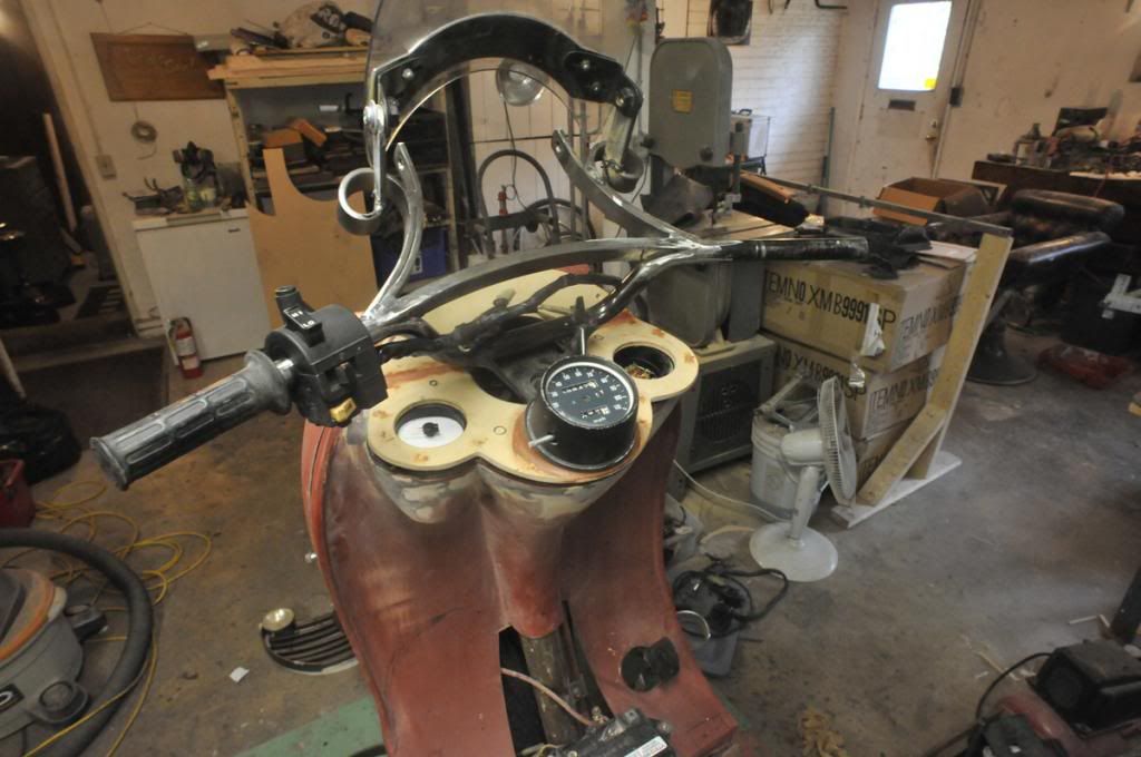 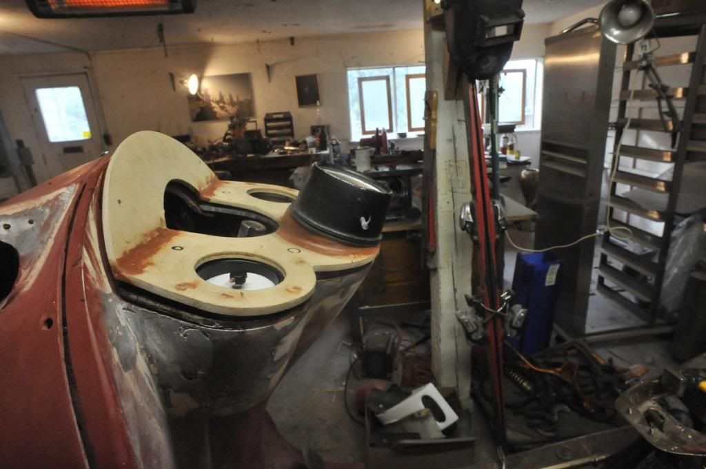 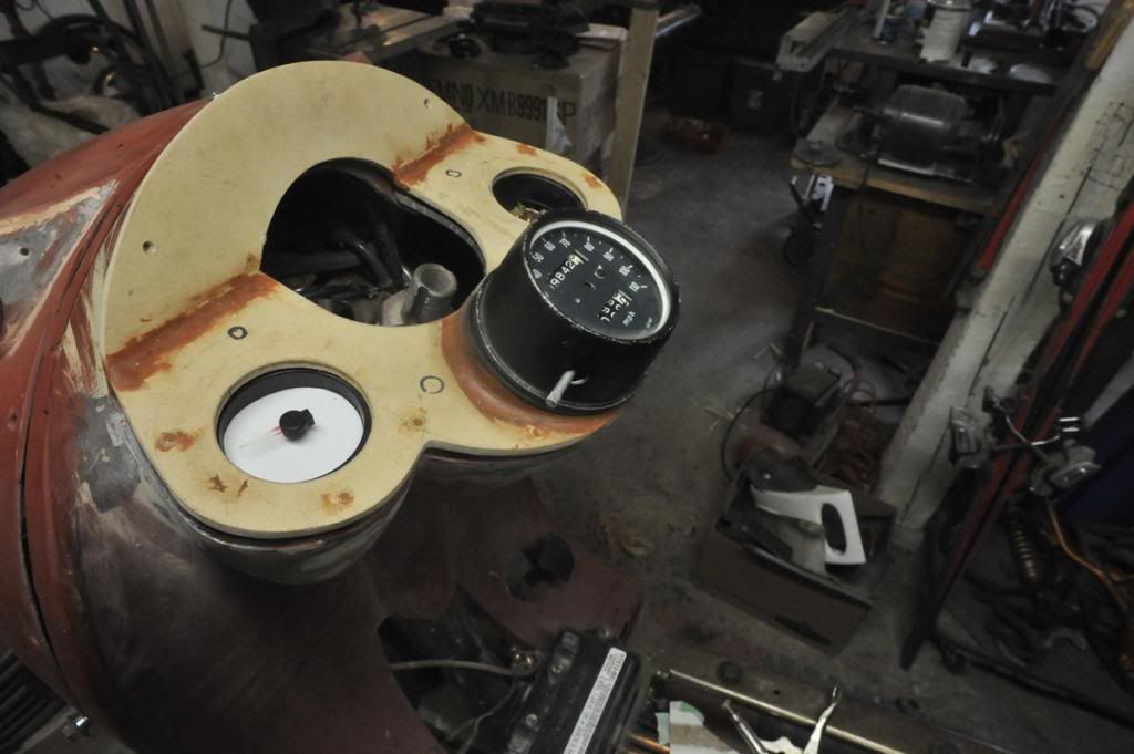 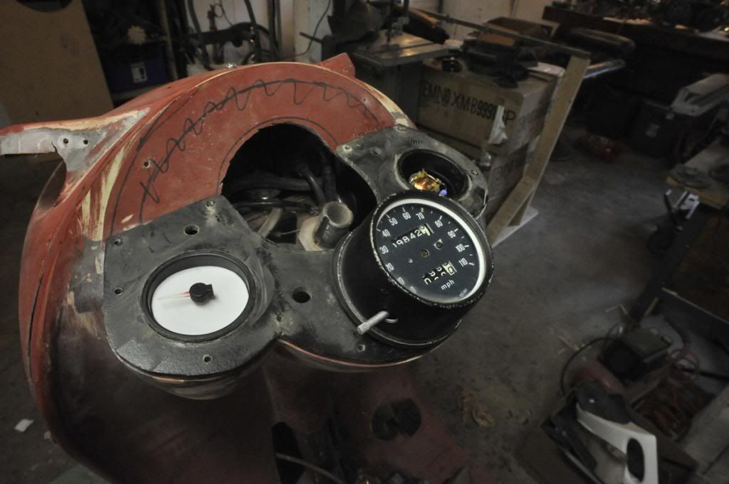 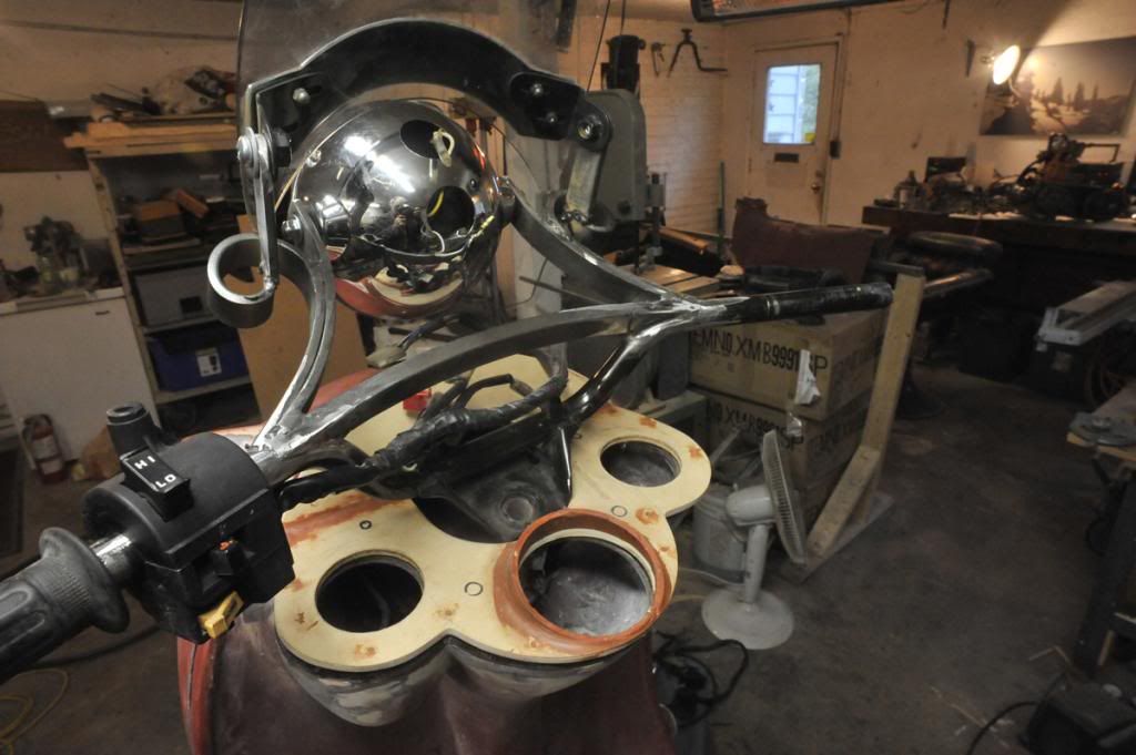 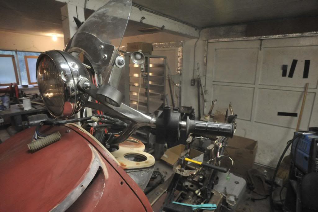 |
|
Junior
  
Currently Offline
Posts: 117
A+'s: 1
Joined: Jan 9, 2012 18:18:11 GMT -6
|
Post by dryshave on Feb 2, 2013 11:21:24 GMT -6
justbuggin, I'm hoping to have it ready for road testing by the end of may, but don't you want to wait until I get all the extra goodies added  and yes madcollie, this is more a new ride..... I wanted to build something totally unique and yet functional and designed for me. You are all welcome to drop by for road testing and tweaking anytime, the only rule is that you have to arrive on two wheels. I decided to go with modifying the gauges for two reasons... the original gauges (fuel/temp) work with the original sensors, so no messing around and I used to work with a company (that produced artwork for another company) that did automotive gauge conversions (miles to km) locally. I'll take some close up pics of the pieces as they go back together. All I need to do is transfer the artwork onto clear acetate (copy/print) and that gets sandwiched between an opaque layer and a glass layer... it's more complicated to describe than actually do. Once I had taken one of the gauges apart, it was clear how they did it originally. I would have liked to have kept the digital speedo, but far more complicated in relocating the odometer and trip meter. My past "completed" hemrod projects: 1966 Olds Dynamic - super rocket 1961 Chevy Impala 1951 Chevy 3100 "PEARL" 1961 Vespa VBB 1985 Honda V45 sabre 1985 Honda V65 sabre - fastest bike I've ever ridden, scared the hell out of me. 1985 Honda VT500 (x2) - fun bikes, great towners 1985 Honda Elite 150 (x3) incompleted 1961 T-Bird - my one regret 1960 Jaguar MK9 - should have done my research first |
|

