|
|
Post by JR on Jun 23, 2013 19:05:14 GMT -6
Alright, time for Jeopardy again. Seems like the knowing how to fix a scooter better than others guy that owns a Fashion is at a loss to help the guy who gave up so long ago. Now we don't have the last thread that this gentleman put up to help because like he said it somehow got deleted? Imagine that? scooterdoc.proboards.com/index.cgi?board=250cc&action=display&thread=8106&page=1Lets see who can hit the daily double!  JR |
|
|
|
Post by alleyoop on Jun 23, 2013 19:59:19 GMT -6
My guess is his solenoid is bad internally or his ignition is toast.
Alleyoop
|
|
|
|
Post by cruiser on Jun 23, 2013 20:42:17 GMT -6
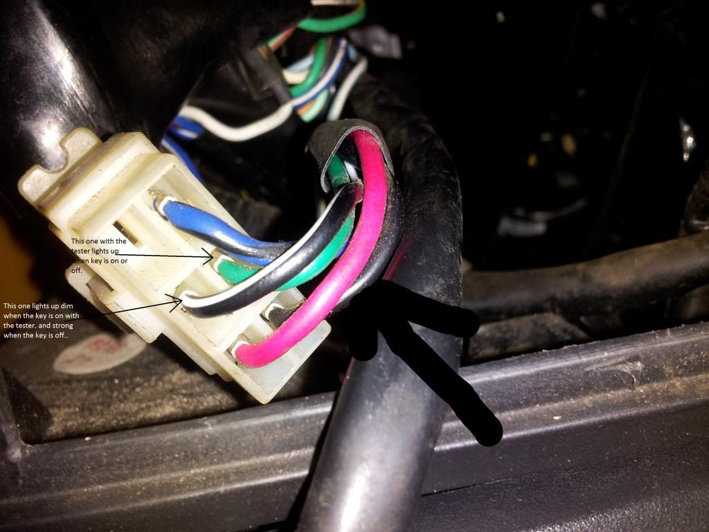
All the readings for the black wire and the green wire were OK. The reason he was getting such weird results is that he is using the tester incorrectly. In order to use the tester, it should be clipped to a ground point or the negative terminal of the battery. The pointy end will light up the light whenever you probe a 12 volt source.
The readings he did get that were suspicious was the kill wire (B/W) having some voltage on all the time.
|
|
|
|
Post by JR on Jun 23, 2013 20:43:57 GMT -6
Well he has posted on the Ride so I'll ask him some questions. Since his other thread was deleted I'll have to start from scratch so to speak. Where's the all knowing Fashion owner help over there at?  D8 JR |
|
|
|
Post by JR on Jun 23, 2013 20:56:22 GMT -6
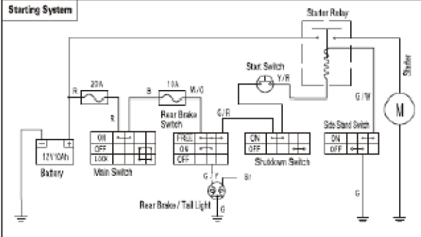
All the readings for the black wire and the green wire were OK. The reason he was getting such weird results is that he is using the tester incorrectly. In order to use the tester, it should be clipped to a ground point or the negative terminal of the battery. The pointy end will light up the light whenever you probe a 12 volt source. The readings he did get that were suspicious was the kill wire (B/W) having some voltage on all the time. Agree but the problem I have is knowing which version he has. I don't remember if he said this scooter was OK when he got it or if this problem started after he got it? again the info on the original thread is gone? There are two versions, one with a head light on/off switch and the other with the headlights on all the time. And it's possible that he got a voltage reading on the black wire to the black/white kill wire through the CDI because this scooter has a side stand switch which grounds out the CDI also. Actually according to the diagram the side stand switch is a two way NO/NC switch which grounds out the CDI when down and opens the starter circuit to the starter solenoid. When up it un-grounds the CDI and closes the ground circuit to the starter solenoid. JR |
|
|
|
Post by alleyoop on Jun 23, 2013 21:12:55 GMT -6
|
|
|
|
Post by JR on Jun 23, 2013 21:26:22 GMT -6
Helpful info Alley thanks.  JR |
|
|
|
Post by JR on Jun 23, 2013 21:57:12 GMT -6
 OK this confirms what I said and it's easy to understand. Red = 12Vdc from batter to key switch Black - 12Vdc with key on Green = ground Black/white = engine kill wire He says light bright to the green wire with the key on or off so that could only be testing the red wire. He says bright with the key off from black/white to red and that would be correct because with the key off the black/white is grounded. He says dim with the key on from black/white to red, that is a back feed through the CDI. The light will go off if he unplugs the CDI. Voltage on the black wire with the key off = bad contacts in the key switch plus it won't run like this, reasons? With key off CDI is grounded out even if he has voltage on the black wire and this is also why the lights are on with the key off. When he turns the key on he un-grounds the CDI but has no voltage to the CDI. JR |
|
|
|
Post by JR on Jun 23, 2013 22:30:03 GMT -6
 Please look at the diagram of the starting system on the CfMoto Fashin and tell me what's wrong in the picture below? Please look at the diagram of the starting system on the CfMoto Fashin and tell me what's wrong in the picture below?  |
|
|
|
Post by JR on Jun 25, 2013 15:59:12 GMT -6
That is a picture posted on Doc of the solenoid starting relay and according to the diagram it's marked correctly except....... one terminal.
G/W is the side stand switch that does supply the ground side of the starting relay once the stand is raised
Y/R is the hot wire coming to the relay from the start button which also routes through either brake like switch and the engine shut off switch.
The fuse layout looks correct.
But I'm real confused on the two large main terminals? One is listed to the battery, and the diagram confirms it and there is a "B" on the post indicating to the battery.
But the other terminal with a negative side circled with a black marker and listed as NEG to ground? The diagram says to Motor which equals starter motor and if you again look at the letter on the relay it is marked with a big "M".
So if this is indeed hooked up that way on this posters scooter what happens when you engage the relay. Since we know that a starter relay is only a magnetic switch that sends voltage from one terminal to the other what happens when you combine the positive battery post to the negative battery post? Don't think the starter will turn over?
Also a common practice when testing for a possible bad starter relay is to just cross the two main terminals with say a screwdriver sending 12Vdc to the starter. If the starter engages then it's highly possible the relay is bad. I sure would hate to cross these two terminals in this picture. Yikes!
OH well?
JR
|
|
|
|
Post by tvnacman on Jun 25, 2013 20:04:58 GMT -6
Please check the battery terminals + and - and be sure the cables are connected correctly . Even disconnect the battery cables and do a voltage reading on the battery .
John
|
|
|
|
Post by JR on Jun 25, 2013 20:23:18 GMT -6
John this is a picture of the starter solenoid relay with a explanation of what each terminal is from Doc. Point blank if the diagram is right and I know no reason it isn't then this explanation is clearly wrong and if anyone hooks it up this way they are going to melt down something if it is engaged for any period of time and/or possibly blow up a battery.
JR
|
|
|
|
Post by alleyoop on Jun 26, 2013 22:17:47 GMT -6
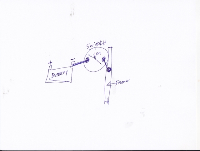
Here is how his switch should be connected: He explained how he did it and it is wrong. What he actually did is UNGROUND the Battery. Alleyoop He can still use the DISCONNECT off the NEG like you had it BUT: 1. Take the Cable from the NEGATIVE POST off the FRAME(LEAVE IT ATTACHED TO THE NEG POST ON THE BATTERY). 2. ATTACH THAT END TO YOUR SWITCH. 3. Take anothe piece of wire and put it on the other terminal on the SWITCH and attach that WHERE YOU TOOK OFF THE GROUND WIRE FROM THE BATTERY. So NOW when you turn the DISCONNECT SWITCH to work IT COMPLETES THE GROUND CIRCUIT TO THE BATTERY. When you take the KEY OUT it then DISCONNECTS the BATTERY GROUND. Alleyoop  |
|

