New Student

Currently Offline
Posts: 27
A+'s: 0
Joined: Jul 29, 2011 16:51:14 GMT -6
|
Body work
by: n4zou - Dec 19, 2011 16:32:28 GMT -6
Post by n4zou on Dec 19, 2011 16:32:28 GMT -6
|
|
New Student

Currently Offline
Posts: 27
A+'s: 0
Joined: Jul 29, 2011 16:51:14 GMT -6
|
Post by n4zou on Oct 25, 2011 19:47:01 GMT -6
I was involved in a very bad accident on my JCL 250A scoot. The driver coming toward me on a narrow road lost control while travelling at an excessive speed. The car started doing 360's toward me and I had no way to avoid it. After I determined that I could possibly avoid it by moving to the left lane I started heading that way putting me at about a 30 degree angle to that car. I "almost" made it. I was hit on the right side of the scoot with the drivers (Left) side of the door. The scoot and I was thrown violently into the side of the car and then across the handlebars and through the scoots windshield when it hung-up on the drivers side mirror. Due to the scoots step through design my leg/body was not crushed between them as would have happened on a "classic" motorcycle. I was actually able to stand up and walk away from it altho I suffered bruising of my torso and ribs. After 30 days I'm still suffering from bruised ribs. My doctor does not understand why they did not break from the forces involved. He also told me to expect some level of pain from them for at least 3 months and possibly for as long as 6 months. I'm currently shopping for another scoot. I keep looking at different models but for some reason I keep wanting another, still available, 2007 JCL 250A.
|
|
New Student

Currently Offline
Posts: 27
A+'s: 0
Joined: Jul 29, 2011 16:51:14 GMT -6
|
Post by n4zou on Oct 25, 2011 19:09:42 GMT -6
The Chinese are famous for doing things on the cheap. That is the cause of the electrical problem you are having. There should be no soldered connections in 12 volt DC wiring harnesses. That's all the Chinese do! I also had the same problem you have. The fix was cutting out all the soldered connections and replacing them with compression type butt connectors. The problem with Chinese soldered connections is they don't bother to twist them together making a solid copper to copper connection before soldering. They just stick the wires together and "glue" them with solder. You end up with solder between the wires and no copper to copper connection. Eventually the connection fails because the solder gets old and becomes a resistor. On my JCL 250A I started at the high and low beam wires coming from the high/low switch on the handlebar. I had to remove the instrument cluster to get to them. I simply removed all the mounting screws and left all the wires connected allowing it to hang out of the way. I cut every soldered joint and reconnected them using butt connectors. I then moved on to the headlight wiring harnesses too. Any automotive retailer will have butt connectors and the crimping tool for them. Usually they sell them in a kit with the crimping tool and an assortment of connectors. This might be a good time to install relays for the headlights, brake lights, and the radiator fan too. Having been an electronics tech and an electrician I got fancy with my relays. I used an extra relay and turn signal flasher connected to the passing light switch. When I pull in that switch the left and right high beam filaments flash alternately left and then right. You need a single poll double throw (SPDT) relay and a turn signal flasher that does not have the blown bulb feature so the relay alternates on/off at normal turn signal flash rated speed. I also use the same circuit on my stop lights. When I pull in the brake lever activating the brake lights the right and left brake lights alternate on and off. This really makes people notice your stopping. It's really simple to implement. Take one standard automotive SPDT relay and connect it like this using this picture of the relay and it's numbers. forum.allaboutcircuits.com/image_cache/httpi27.tinypic.comoj3rsh.jpg From the headlight passing or brake light switch connector that connected to the lights connect a 5 amp fuse. From the fuse connect to the +post on the flasher. From the flasher load post connect to relay terminal 85. Ground relay terminal 86. Run a second wire from the headlight switch and connect it to a fuse appropriate for the load of the headlight or taillight. From the fuse connect the wire to relay terminal 30. Connect one headlight high beam filament or brake light filament to relay post 87 and the other headlight high beam filament or brake light filament to relay post 87A. When you activate the passing or brake switch you energize the flasher can. The flasher can will turn the relay on and off as it would turn signal lights. In this case when the relay is off the light connected to 87A will turn on. When the flasher can turns on the relay the light connected to 87A will turn off and the light connected to 87 will turn on. Not only will you get noticed but the load on switches will be reduced by half as will be the load on the electrical system when they are used. |
|
New Student

Currently Offline
Posts: 27
A+'s: 0
Joined: Jul 29, 2011 16:51:14 GMT -6
|
Post by n4zou on Sept 21, 2011 16:43:21 GMT -6
My MP-250A-JCL is now a wrecked pile of junk.  It saved me from serious damage, perhaps even my life.  An out of control car running about 45 mph while spinning 360's hit me on the right side of my scoot. I should have serious injuries but I don't. I have a few scratches and I'm sore as hell but nothing is broken. The Plastic body on my scoot absorbed most of the impact. The frame is bent as are both wheels. I actually stood up and walked away from it. Witnesses asked me why I was not dead. Due to the body design providing a nice wide gap between the car and the scoot, nothing got crushed. As soon as I'm over the soreness I'm going to order a new Scoot exactly like the one I had. |
|
New Student

Currently Offline
Posts: 27
A+'s: 0
Joined: Jul 29, 2011 16:51:14 GMT -6
|
Post by n4zou on Aug 19, 2011 20:22:04 GMT -6
Scooter and Motorcycle tires use very soft rubber for maximum grip on the road surface. This is the reason they wear out so fast. Back in my Harley Davidson days I would put automobile tires on my Road King. The only problem I had was when it rained. It was like riding on ice. When the roads were dry that car tire worked just as good as a soft motorcycle tire. Something else to remember is weight. A fully dressed out HD bagger weighs about the same as a Smart Car! A scoot may simply not weigh enough to allow a hard car tire to get a proper grip even when it's dry. I do ride my scoot a lot and usually put two new tires a year on the rear of mine. I change them myself. I have a couple of tire irons, a 6" c-clamp, and a bench vice I use to break the bead. First thing you do is remove the valve core and let all the air out. Next open the vice up and put the tire in between the jaws being careful not to mash the wheel along with the tire. Once the bead is loose put the wheel on a good solid table with the disk rotor down. Stick your irons in and start pulling the bead over. This is where that C clamp comes in handy! If your having trouble getting the bead over the rim put the c clamp on the tire and squeeze the beads together so they can drop down further in the rim. This will provide clearance so the bead opposite the side of the c clamp will come over the wheel rim. Now is a good time to change the valve core if it looks dry rotted or damaged. Now clean the inside of the wheel in preparation for installing the new tire. Make sure you put it on correctly looking for a direction arrow on the tire! Also look for a small painted dot or three painted dots on the tire. These dots mark the light side of the tire. Look on the wheel for a mark indicating the heavy side. If it's not marked you can find the heavy side by putting the wheel on a shaft that will allow the wheel to spin freely so the heavy side will coast to gravity. Now take a file and mark a small line so you never need to find it again. I use Armor-All as a lubricant. Spray it on the beads of the tire. Avoid getting it on the parts of the tire that will be on pavement! If you do get it all over the tire use some soap and water to remove it after installing the tire. Line up the paint marks on the tire with the heavy side mark on the rim and push the tire on. The first bead should go on easily. Now start the second bead on the wheel. Grab the c clamp again and use it to again press the beads together making sure it will not hit the wheel rim at any time. Now using your tire irons work the second bead over the rim one after the other working toward to c clamp. The C clamp will prevent the bead from walking away as you work it in. As soon as the bead pops in you can air it up and balance the wheel and tire if you have the wherewith all to do that. Usually it's close enough not to bother with on small diameter scooter tires.
|
|
New Student

Currently Offline
Posts: 27
A+'s: 0
Joined: Jul 29, 2011 16:51:14 GMT -6
|
Post by n4zou on Jul 30, 2011 11:17:58 GMT -6
That's a nice compact cooler, Scott. Where on the scoot did you mount it? Did it take care of all your cooling problems? Was it difficult to bleed the air out of it? The radiator on my TANK was located behind the fuel tank right in front of the engine. This model was notorious for overheating. The radiator placement does not allow natural air flow across the radiator. There was plenty of room to mount it behind the grill in front of the fuel tank where the radiator should have been mounted anyway. I used standard heater hose from Autozone to hook it up in line with the stock radiator. I had to make some hose adaptors because the radiator had 1/2 nipples but the stock radiator used 5/8 heater hose. I routed the hose from the water pump to the new radiator and hooked the hose to the lower fitting with a 5/8 to 1/2 inch adaptor between. The upper and now outlet from the new radiator was also fitted with a 1/2 to 5/8 adaptor. On this adaptor I drilled and tapped a 1/8 NPT hole and a 1/8 pipe barb. I ran 1/8 hose and put a 1/8 "T" into the 1/8 hose connected to the radiator cap neck. This bleeds air from the new radiator because the upper outlet of the new radiator must connect to the bottom radiator on the stock radiator which would trap air. The small diameter hose used does allow a little coolant to bypass the stock radiator but it's so small and the amount of coolant so little that it makes no difference in cooling. You could install a small valve and shut it off after bleeding out the air but There really is no reason to bother with it. Anyway the new radiator is now connected to the stock radiator. I had no problems burping the air out of the system. I never had any cooling problems after adding that radiator and the fan would actually cycle on and off according to stop and go or very slow operation. The fan would never turn on while running on an open road above 30 MPH even on 90+ degree days. The only downside was it took a long time for the engine temp to get up to operating temp during the winter. This made an impact on fuel mileage so I installed a valve and bypass line so I could disable the add-on radiator when the ambient temperature was below 50 degrees. I do ride year round even when the temps are below freezing. |
|
New Student

Currently Offline
Posts: 27
A+'s: 0
Joined: Jul 29, 2011 16:51:14 GMT -6
|
Post by n4zou on Jul 30, 2011 8:29:16 GMT -6
The people that assemble these Chinese scoots are paid by the number they roll off the line. They do not take the time to make required adjustments as they assemble them. With this in mind do not assume the brake was properly installed and inspected at the factory.  The disk brake calliper has a butterfly spring that exerts a slight pressure on the pads to force them apart slightly when you release the brake lever. Remove the pads from the calliper and look at that spring. It should exert equal upward pressure on the pads and a couple of little tabs should engage the pad exerting lateral pressure that pushes the pad opposite the pad that contacts the brake pistons. This spring keeps the calliper centred between the pads and disk as the pads wear down and slightly pushes the pads apart when the brake lever is released. An improperly installed or bent spring will cause uneven pad wear, a brake that never fully releases, and/or squeaking. While you have the brake calliper apart clean and apply a little grease on the pins the calliper slides on. These pins are located on the bracket that holds the calliper. It is very important that the calliper slides freely on these pins! Don't apply so much grease that will end up on the disk and pads. You only want a thin film on the pins and just a little inside the rubber seals that keep water, dirt, and brake dust away from these pins. I use marine grade water proof grease. Some people like to use other types of grease and that’s fine as long as that grease will not dry out over time or is susceptible to water contamination. We've all rode in the rain at some time and perhaps gotten a little carried away washing and rinsing it. |
|
New Student

Currently Offline
Posts: 27
A+'s: 0
Joined: Jul 29, 2011 16:51:14 GMT -6
|
Post by n4zou on Jul 29, 2011 20:18:53 GMT -6
While I was in High School I went to trade school at night to become a machinist. I went to work in a ship yard immediately after leaving HS. After a few years of being an inside machinist I lost my job due to economic (recession) problems. I consequently enlisted in the US Navy and became a Gas turbine systems Tech. I qualified in all areas or mechanical, electrical, and electronics systems. After 6 years the US Army recruited me to work on M1 Abrams Tanks. I worked for the Army for 19 years before retiring. When I started I only worked on the AGT-1500 turbine engine and transmission "power pack". As the years progressed I qualified to work on the entire Tank including fire control and the M1-A2 heat vision system. Before I went in the Navy I had purchased a lathe and mill and leased them to a machine shop. In 2007 the machine shop that leased them went out of business (another recession) and I was told that I had to remove my machines or they would be sent to a scrap yard. Needless to say I went and moved my machines and build a shop to house them behind my house. Those machines repaid there original cost after many years on lease.
|
|
New Student

Currently Offline
Posts: 27
A+'s: 0
Joined: Jul 29, 2011 16:51:14 GMT -6
|
Post by n4zou on Jul 29, 2011 19:55:10 GMT -6
|
|
New Student

Currently Offline
Posts: 27
A+'s: 0
Joined: Jul 29, 2011 16:51:14 GMT -6
|
Post by n4zou on Jul 29, 2011 19:25:46 GMT -6
|
|
New Student

Currently Offline
Posts: 27
A+'s: 0
Joined: Jul 29, 2011 16:51:14 GMT -6
|
Hi all!
by: n4zou - Jul 29, 2011 18:45:03 GMT -6
Post by n4zou on Jul 29, 2011 18:45:03 GMT -6
Real name is Scott and I am located in Alabama. My current scoot is an MP-250A-JCL with a VOG clone engine. Current mileage is 14,000 Miles. My prior scoot was a TANK with a 244cc CFMOTO engine. At 60,000 Km it suffered a burned ignition pickup that also took out the electronic control module. The radiator had developed tiny leaks and needed to be replaced. Along with that the headlight housing started cracking and fogging and the plastic body panels were crapping out too. It would have cost me more to fix it up than buying my new MP-250A-JCL scoot so that's what I did. Other than adjusting the valves on the VOG engine I like my new scoot much more than the old Tank.
|
|
New Student

Currently Offline
Posts: 27
A+'s: 0
Joined: Jul 29, 2011 16:51:14 GMT -6
|
Post by n4zou on Jul 29, 2011 18:12:49 GMT -6
After 13,000 miles my stator burned out one phase. I noticed it was not properly charging the battery. Battery voltage was only 12 VDC at idle with only a very slight increase when running the RPM up a little over idle. I knew then I had a bad stator but I double checked just in case the voltage regulator was shorting out that phase. I unplugged the stator output connector while it was running and checked across each of the 3 output wires. Voltage output was only 5VAC on one of the 3 phases. I went ahead and shut it off knowing it was going to be a while before I received a replacement stator. I went ahead and drained the carburetor and removed the battery. I then went in and order a new stator from the dealer I purchased my scoot from. It cost $44 + $12 shipping. After ordering I went ahead and pulled the Right lower body panel, muffler, and that air valve pollution control system connected to the exhaust port on the head. All must be removed to remove the right side engine cover containing the stator. I used some card board as a cover bolt placement guide because not all the bolts holding the cover on are the same length. Make sure you drain the oil before you remove that cover! Also be sure and clean the cover and engine area so you don't get road grime in the engine when you remove it. Removal was easy. (It was much easier than the 244cc CFMOTO engine.) After you remove all the bolts you'll need to look for some little tabs around the cover that allow you to pry it off without needing to pry on the sealing surfaces. Because the stator is mounted in this cover and comes off with it the magnets in the magneto will exert some force as you pull it off. (Also parts will not come flying out and rolling around on the floor like the CFMOTO engine.) 3 bolts hold the stator in the cover and 2 bolts hold the ignition pickup. You'll need to remove both. You'll get a new ignition pickup with the new stator so you will not need to worry about pulling new wires through the rubber plug. This is the easiest stator replacement I have ever done! Whoever designed this had to work as a mechanic at some point in his career. Lucky for me the gasket remained on the engine and was not damaged. When I put the cover back on I just stuck it on and bolted it in place. I had no oil leaks at all. Here are pictures. 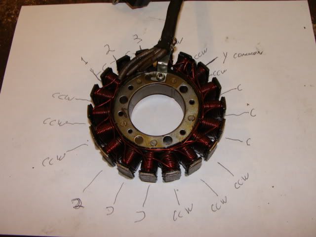 The bad stator. I thought I might one day rewind this stator myself. This photo tells me how to do that. 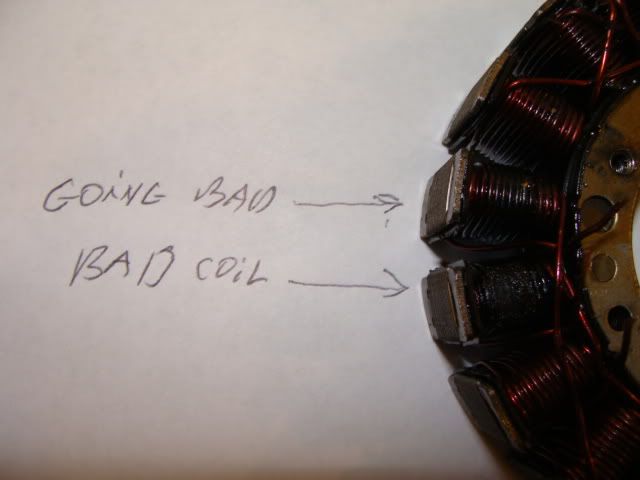 I've never figured out why the poles that burn up are not the ones that have windings shorted to the stator frame. They seam to always be the poles that are connected to the output wires. 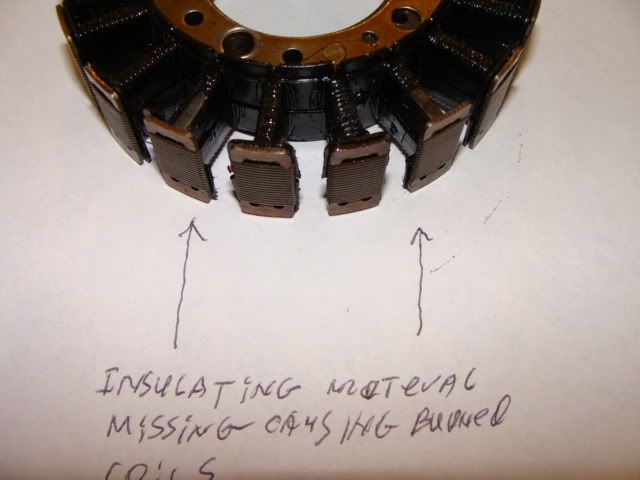 Whoever wound this coil broke the plastic insulating material and went ahead and wound it anyway. This is what caused the stator to burn up. 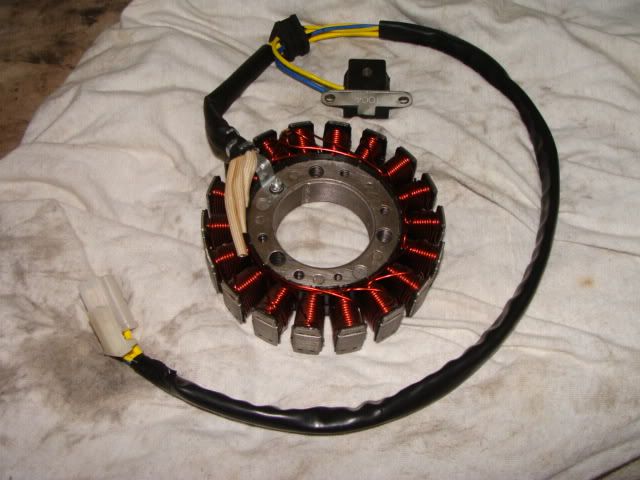 This is the new stator. It was wound by someone that took great care to do it properly. I don't think this one will burn out before I wear out this scoot.  The new stator and ignition pickup bolted in the cover and ready to be put back on. Note the pry off tab at the bottom right on the cover. 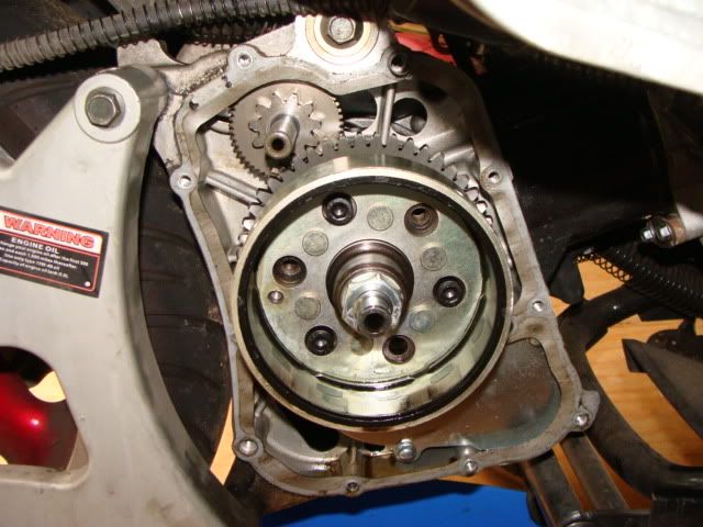 Here is the engine side. Note how the oil line is incorporated into the case instead of the external oil line used on the 244cc CFMOTO engine. That made this job so much easier and faster. While I was at it I made a block off plate for that air valve hooked up to the exhaust port. You can see it under the two shiny bolt heads at the right side of the picture above. Idle is much improved and I gained 5 MPG fuel economy. That block off plate was a pain in the ass to machine. It requires 4 precise 10 degree angles to be milled off and the ends must have a radius filed by hand so it matches the tube flange exactly. I could have simply cut the tube from the stock flange and used sheet metal to block off the exhaust port. I did not want to do that just in case removal of that pollution control system caused a performance problem. I am not in California so this system is not required in my state. If you are in California make sure you reinstall this system. I also had to make a spacer for the case bolt used to hold the valve to the engine. Yes; I have a lathe and mill for making special parts. I do not make parts for sale however, so don't even ask. |
|

